| “This site contains affiliate links for which OEMDTC may be compensated” |
| Group
ENGINE MECHANICAL |
|
| Number
01-20-002-1 |
|
| Subject
2001 SONATA/ SANTA FE 2.4L ENGINE RUNS ROUGH, IDLES ROUGH, DTC P0335 |
Date
OCTOBER, 2001 |
| Model |
This TSB has been revised to add a procedure to index the oil pump / balance shaft sprocket. Not properly indexing the sprocket may cause an engine vibration, mostly noticed at 3500-4000 rpm. The warranty information table has also been changed.
DESCRIPTION:
Some 2001 MY 2.4L Sonata and Santa Fe vehicles, customers may complain of one or more of the following conditions:
- Rough running.
- Rough idle.
- Lack of power at low rpm.
- Check engine light on (DTC P0335 crankshaft position sensor malfunction).
This condition may be caused by the exhaust camshaft coming out of time.
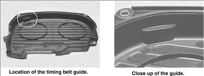
A new timing belt cover P/N 21360-38214-D ![]() that incorporates a timing belt guide has been installed on vehicles produced since January 30, 2001.
that incorporates a timing belt guide has been installed on vehicles produced since January 30, 2001.
Vehicles that experience the condition described above should be updated with the new timing belt cover
INSPECTION:
- Inspect the production date of the vehicle. Vehicles produced on or after January 30, 2001 are not affected by this TSB.
- Remove the upper timing belt cover.
- Rotate the crankshaft until the timing mark of the intake cam sprocket is aligned with the timing mark on the rocker cover.
- Inspect the alignment of the timing mark on the exhaust cam sprocket with the timing mark on the rocker cover:
SERVICE PROCEDURE:
- Remove the right front wheel and engine splash shields.
- Lower the vehicle and support the engine with a floor jack.
- Remove the right side engine mount, water pump pulley, accessory drive belts, and lower timing belt cover.
- Set the engine to top dead center (TDC) and set the intake and exhaust cam sprockets on their timing marks (as close as possible).
- Remove the auto tensioner and timing belt.
- Inspect the timing belt. If its worn, cracked or frayed, replace it.
- Inspect the tensioner. If its leaking fluid, replace it.
- Slowly compress the tensioner in a vise (apply pressure until resistance is felt, allow tensioner to compress, then apply more pressure) until the locking pin can be re-installed. A locking pin is supplied with a new tensioner. If an extra locking pin is not available, a 3/64″ steel pin can be substituted.
- Install cam sprocket holder (SPX/Kent-Moore P/N 09231-38000) to hold the cam sprockets in alignment during timing belt installation. Install the tool 1/4″ deep after the sprocket timing marks are in alignment.
NOTE Insert the tool only 1/4″ to make it easier to remove after the timing belt is installed.
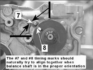
- Set the oil pump sprocket so that timing marks #7 and #8 are aligned. Quickly rotate the sprocket back and forth, between the 9 and 12 oclock position feeling for a centering feel when the timing marks meet. If the sprocket timing mark feels like it wants to move away from the other mark, rotate the sprocket one complete revolution and try it again.Timing marks #7 and #8 will naturally align when the balance shaft is in the proper orientation.
NOTE This step is an alternative to the Shop Manual instructions described on Page EM-89, Step 17, Note #2, in the 2002 Santa Fe Shop Manual. Either method is acceptable.
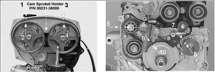
- Verify the following timing marks are aligned (refer to photos below):
- Camshaft sprockets (intake 1, 2; exhaust 3, 4)
- Balance shaft (5, 6) and oil pump sprocket/balance shaft (7, 8)
- Crankshaft (9, 10)
- Wrap the timing belt in a clockwise direction starting from the intake cam sprocket. Keep the belt tight when installing over the exhaust cam sprocket, oil pump sprocket/ balancer, and crankshaft.
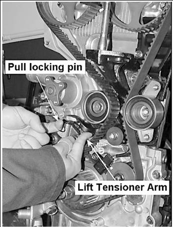
- Apply hand pressure to the tensioner pulley to take up any slack, and remove the lock pin from the tensioner. Remove cam sprocket holder.
- Rotate the crankshaft clockwise (by hand) 2 complete revolutions and set to TDC. If the TDC mark was passed, then rotate the crankshaft another two complete revolutions. The crankshaft must only be turned clockwise for proper tension and orientation of the timing marks.
- Inspect the timing marks of the cam sprockets for proper timing.
NOTE Due to the difference in ratio between the crank sprocket and the oil pump sprocket, the oil pump sprocket will appear out of time after turning the crankshaft 2 revolutions (provided the sprocket was set properly in steps 8 and 9). The oil pump sprocket will come into alignment on the 6th revolution (1 : 1.5 ratio; crank to oil pump).
- If the timing marks are properly timed, rotate the crankshaft an additional 90 degrees to take the marks off of TDC.
- Reassemble the engine (if applicable) and install new timing belt cover P/N 21360-38214-D
 .
.
WARRANTY INFORMATION:
NOTE
Only one of the two Operation Codes below can be claimed for this repair. Both operation codes CANNOT be claimed for the same repair/claim since Operation Code 24312R00 (Timing Belt Cover Replacement) is already included in the time to perform Operation Code 21361R00 (Timing Belt Replacement). Use Operation Code 21361R00 (Timing Belt Replacement) if the Timing Belt is replaced. Use Operation Code 21361R00 (Timing Belt Cover Replacement) if the Timing Belt is not replaced, but only the Timing Belt Cover is replaced.
| OP CODE | OPERATION | OP. TIME | OP. QTY | NATURE CODE | CAUSE CODE |
|---|---|---|---|---|---|
| 21361R00 | Timing Belt Cover Replacement | 0.2 | 1 | N02 | C24 |
| 24312R00 | Timing Belt Replacement | 1.7 | 1 | N02 | C10 |
 Loading...


